


Experimental results of field test vehicles
The results demonstrated in the following paragraphs have been achieved within the INTEROP joint research project by scientific lab tests and field test operation.Vehicles and secondary pads
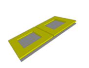
One of the most important special features of the WiPT-standard
interoperability definition is the ability to design mechnical and
magnetically different secondary pads exactly adjusted for the desired
vehicle. Nevertheless, all of them can be operated on a
standardized magnetic energy source, the primary pad.
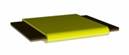
Design roules are provided to adjust the secondary pads to different
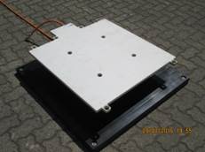
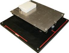
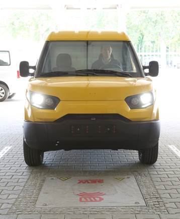
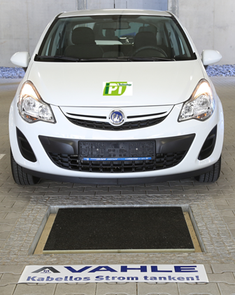
mechanical space and ground clearences required by different vehicles.To demonstrate and to verify this feature of mechanical flexibility of the interoperability definition four different vehilcles have been equipped with very different secondary pads. Especially concerning the pad size extremely different pad have been designed which are listed in the following table together with the vehicles at which the pad are used. Intense scientific research has been executed at the first three vehicle types A to D, whereas C and D distinguished same mechanical and electrical designes prduced by two different manufacturers.
| Pad / vehicle B2 |
Pad / vehicle A |
Pad / vehicle C/D |
Pad / vehicle E |
|
|---|---|---|---|---|
| Secondary coil type |
Double flat |
Double flat | Solenoid |
Solenoid |
| Sekundäre Feldplatte |
 |
 |
 |
|
| Vehicle type |
iMiEV / eOn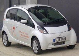 |
Streetscooter B14 |
Cetos (based on Opel
Corsa)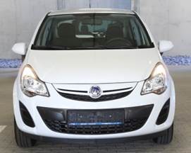 |
Karabak (based on
Fiat 500)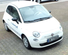 |
A further vehicle indicated with B1 has the same vehicle type as C and D but carries the secondary pad desing of vehicle B2. Therefore one single vehicle type carries pads of very differnt sizes and different coil topologies (double flat and solenoid) thus enabling a direct comparison of the pad designs.
The differences are stated more precisely in the following table, listing the most important technical parameters of the experimentally investigated pads. Apart from different pad sizes the broadly different battery voltages should be noted, also. For the supply device (primary charging pad) the varying nominal battery voltages do not make any difference in its functionality. This feature is similar to AC charging as in this case the vehicle mounted charger adjusts the line voltage to the battery voltage. For DC charging this feature is quite inpossible (or at least technically not desireable) used for fast charging as the charger is located outside the car and cannot specifically designed for different DC voltages.
| Secondary pad |
 |
 |
 |
| Application |
Vehicle B1 |
Vehicle A |
Vehicle C/D |
|---|---|---|---|
| Coil type |
Double flat |
Double flat | Solenoid |
| Case size (length*width) |
750 * 750 mm2 |
700 * 500 mm2 | 750 * 750 mm2 |
| Ground clearance |
150 mm |
156 mm |
146 mm |
| Battery voltage |
400 V |
140 V |
380 V |
| Coupling factor |
0,28 |
0,27 |
0,25 |
| Coupling (magnetic conductivity of the coupling flux) |
203 nH | 205 nH |
166 nH |
| Secondary current linkage (current * winding turns) [Primary current linkage: 120 A] |
154 A |
239 A | 318 A |
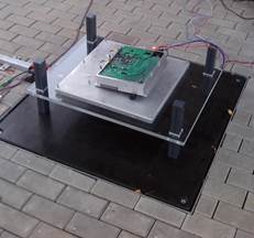
Despite of these lage varying constructive, magnetic and electrical differences all pads and vehicles are able to charge on the primary pads of the supply devices although these primary pads have been produced by two different manufacurers. This is possible as both products are fulfilling the WiPT-standard. This manufacturer independent interoperability is exemplarily demonstrated by the following figure showing Components of all involved technology manufacturers.
Experimentally measured transferred power and efficiency
During a cross exchange test of all possible twelve
combinations of tree supply devices and four vehicles the features of
mixed operation have been measured and verified. Despite the two
operational supply devices shown in the previous figure the third
supply device is the primary reference device build for certification
and lab measurement purposes. This reference device is exactly
constructed according to the mechanical and electrical requirements of
the WiPT-standard.
The operational devices vary in the coil design from the reference
device due to manufacturer specific additional features and production
needs but still fulfill the basic interoperability definition just
specifying the current linkage balance. For that reason the cross test
also proves the choice of defining the current linkage balance as
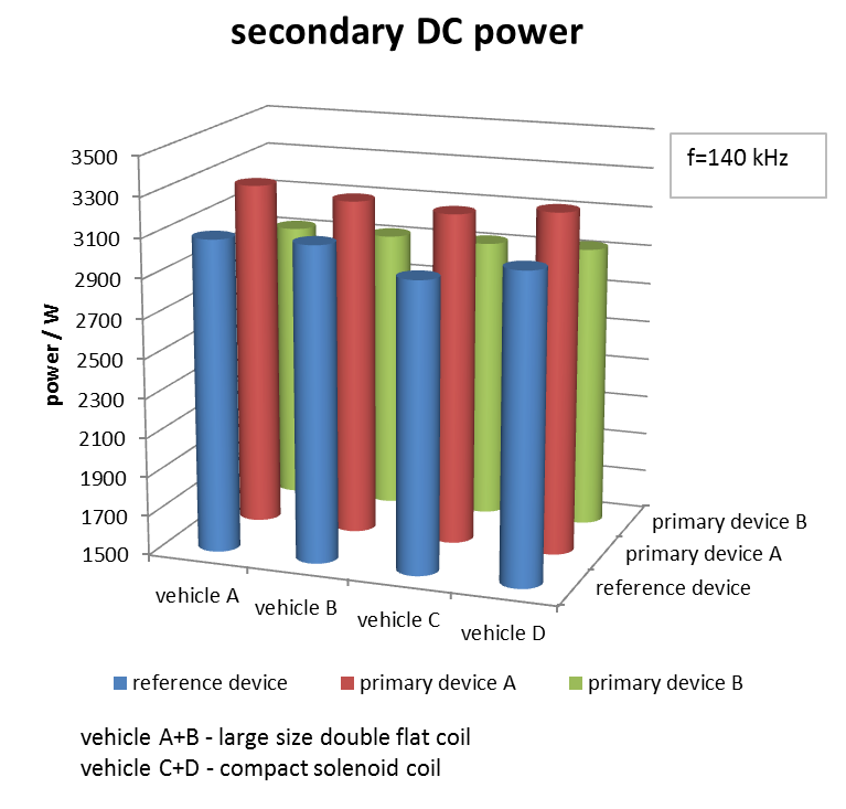
sufficient and not limiting the interoperability.The proof of interoperability in the sense of guaranteeing energy transfer the left figure shows the measured power for all combinations of the cross test. The measured power is the power at the DC terminals of the battery being the relevant parameter for a charging process. For all combinations 3 kW power is reached thus proving the desired feature of interoperability. The visible difference must not be interpreted as quality differences of the design, rather they result from differnt desired operation parameters being variable and free of choice.
The operative supply devices implement an automatic setpoint tracing of the primary current linkage to exactly transfer a choosable setpoint of power drawn from the grid. The two operational supply devices have slightly different setpoints. But due to the setpoint tracing parameter variations due to the four different vehicles are compensated and each vehicle receives the same power on a single supply device. In contradiction the reference supply device does not implement the setpoint tracing and is operated exactly at the nominal primary current linkage value. Due to difference between design consiiderations and practical operation the operation point of transmitted power varies between the different vehicles. Reasons might be a not exact positioning of the vehicle or variance of the ground clearance due to vehicle loading.
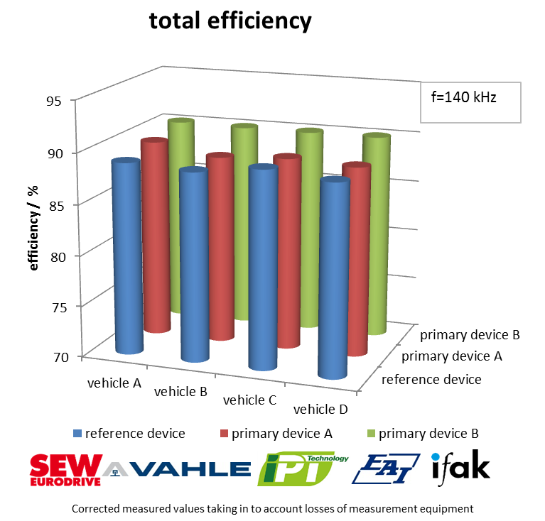
Additionally, the graph on the right side shows the efficiency of the energy transfer also for all combinations of the cross test. The efficiency is measured between the battery terminals and the grid connection point (wall plug). All combinations, even the combinations of manufacturer mixed operaton, reach an efficiency of nearly 90%. Surprisingly for the technology manufacturers the efficiencies do not significantly differ between all combinations although very different designs of secondary devices have been used.