


Interoperability Definition
The concept of the interoperability definition is a source definition. Therefore, all definitions are related to the primary device (primary charging pad) of the supply installation that provides the electrical power. This concept allows for a variable construction of secondary devices (secondary pads) to be adapted to different vehicle constraints as size and vehicle height. A freely chosen secondary design together with the well-defined primary source forms a completely defined electrical transformer whose behavior can be calculated and technically designed. Furthermore, this concept allows a technology independent description as all defined values are physical parameters related to the magnetic interface within the air gap.The definition is structured into the central definition to fix the geometric size and the electrical operation parameters. This central definition is accompanied by a detailed reference geometry aimed to be used for qualification purposes. Furthermore, a few samples for secondary devices are given for informative purpose. These serve as a reference to demonstrate the large variability of secondary devices.
Source definition
Geometric definition
The geometric definition describes the magnetic circuit on the one hand and the position of the windings on the other hand. Within the central definition the winding is not be fixed in detail but only in a neutralized way. The definition assumes the winding is constructed just of a single winding called the current linkage balance and the position is defined just for that single winding. Real windings will differ from that idealized definition but all real windings need to provide a current linkage balance according to the definition. The advantage of such an idealization is that manufacturers are still able to realize specific optimizations to come into a leading market position. Also, different number of turns to adjust for country specific supply voltages can be used without changing the interoperability definition. The defined winding type is a double flat winding. This winding type consists of two symmetrical mirrored circular flat windings distributed over the surface of a ferrite layer. The reference point P needed to calculate the current linkage balance is located on the diagonal line at a quarter of the distance.The central definition assumes an underground installation of the primary device as the definition basically addresses public use where this type of installation is needed and this type of installation is technically much more difficult to solve compared to above ground installation and requires exact surrounding conditions.


This way only very few parameters pointed out within the above figures are needed to define the geometry of the interoperable magnetic source.
Electric definition
The electrical definition defines the operation behavior of the source. The electrical source value is the current linkage. This is the current multiplied with the number of winding turns located between the left and the right reference point. Therefore, half of the current linkage flows through the left part winding and the other half through the right part winding. The reason for choosing the current as the source value instead of the voltage applied to a single winding is the strategy that operation of the source is also possible under no load condition, meaning operation of the primary device without a present secondary device. This is only possible by using the current if a severe oversizing of the supply electronics shall be avoided. This way the behavior of the source keeps well defined even if the secondary device is damaged or doesn’t behave like expected.| Quantity |
Value |
Dimension |
|---|---|---|
| Current linkage (nominal) |
120 |
Arms |
| Operating frequency |
140 |
kHz |
| Grid power (nominal) |
3,3 |
kW |
| Current linkage ramp min. |
250 |
Arms/s |
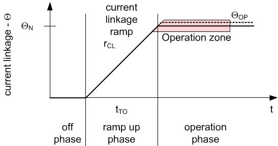
Basically the source definition assumes a current linkage that is either shut down or kept constant at the nominal value during operation. Nevertheless, technical implementations usually do use a controllable current source capable to vary the current apart from the nominal value. This enables a defined ramp up and ramp down phase as depicted in the following figure. Furthermore during constant operation the current linkage can be controlled within a limited range different to the nominal value in order to compensate for tolerances within the system from the nominal situation. This includes e.g. a loaded vehicle reducing the air gap or misalignment of the primary and secondary devices. This variable source value enables a constant power request from the grid under variable conditions to allow the charging to be as fast as possible.
By starting the power transfer with a controllable current ramp turn off conditions can be defined. If no power transfer occurs as expected for a given current a malfunction or a not existence of the secondary device can be assumed resulting in a shutdown of the primary device.
Reference device
To guarantee interoperability of different
systems for wireless power transfer under practical conditions a certification
procedure must be provided. To certificate the widely varying secondary devices
a well-defined and reproducible primary device need to exist for testing. The
central interoperability definition of a current linkage balance is not
sufficient precise for that purpose. Therefore, the reference device aimed for
certification tests exactly defines the current distribution over the surface
including a real winding structure.For the reference device a triangular current distribution is chosen as this type of current distribution delivers a quite homogeneous flux density distribution achievable for scientific investigations.

An exact real winding structure providing such a distribution is given in the following figure.

Sample secondary devices
Within this clause two exemplary secondary
devices for energy reception of a vehicle or mobile containment are presented.
These samples are not a direct part of the interoperability definition but
serve for system analytics and may be used to evaluate different real
implementations of primary devices. The sample devices have been chosen to show
the large variety of secondary device sizes, following in large variations of
the magnetic circuit.The first sample device is optimized for least possible flux densities within the air gap, the second sample device is minimized in size.
Flux density reducing secondary device
A reduction of flux density is reached by using a relatively large area for wireless energy transfer. For this case the secondary device also contains a double flat winding structure. The following figure shows such an arrangement whereas a homogeneous winding distribution within the winding area has been chosen.
Small size secondary device
A winding type providing still acceptable coupling factors at very small size is a solenoid winding. For analyses a size of 33 cm in square has been chosen as depicted in the following figure. To reduce stray fields on top of the solenoid winding a not depicted aluminum shield has to be provided above the device. This shield mirrors the magnetic flux to the ground and thus increases the coupling. The area of the shield must be significantly larger compared to the ferrite size. Dimensions are provided at corresponding calculations. The solenoid carries a homogeneously distributed winding.
Control
Even for energy saving reasons it is necessary
to deactivate the primary device in case no secondary device is present in
order to avoid losses. Therefore, the primary device needs to be activated or
deactivated on a certain command provided by the energy receiver. This clause
describes the definition of this command structure.Interoperable devices require a binary signal that is sent from the vehicle as energy receiver and is received by the primary device as the magnetic energy source. The activation of the source is only executed in case this signal is received. An important requirement to that signal is a limited receiving distance as signal reception must only be possible if the secondary device is properly aligned over the primary device. This feature also makes sure only the vehicle actually being placed over the primary device is able to activate the source.
This signaling is realized by using a frame signal coil located in the center of the primary and secondary device. In case the secondary frame coil is activated by a voltage of a defined high frequency the primary device frame coil receives an induced voltage. In case a defined trigger level of the received voltage is reached, the primary device is activated. This kind of signal sending and receiving is called a point to point or peer to peer signal (P2PS) from the vehicle to the source.
This activation signal is a mandatory element of the interoperability definition.
